Multi-layer ceramic capacitors (MLCCs) are specified by a combination of electrical and mechanical parameters that determine whether one part can be substituted for another. When sourcing teams need to replace a discontinued or allocated part, or when design engineers want a second source, a systematic cross-reference approach prevents costly qualification failures. This guide explains the four-parameter matching method and provides a practical framework for identifying equivalent MLCCs across major manufacturers.
A common sourcing mistake is to search by capacitance value alone. An 0.1 µF MLCC in a 0603 case from one brand may behave completely differently from another brand's 0.1 µF 0603 part if the dielectric, voltage rating, or internal electrode construction differs. Ceramic capacitors exhibit significant capacitance loss under DC bias—a 10 V-rated X7R part may retain only 40% of its nominal capacitance at 5 V. Two parts with identical labeled capacitance but different voltage ratings will have different effective capacitance at the same bias point.
The four parameters that must be aligned are: (1) package size, (2) nominal capacitance, (3) rated voltage, and (4) dielectric class/temperature characteristic. A fifth parameter—case thickness—matters for high-capacitance parts where stacking height affects placement, but it is secondary to the core four.
EIA-198 standardizes MLCC package sizes by length and width in inches. The most common sizes are:
When cross-referencing, confirm that the replacement part's length and width tolerances do not violate the PCB land pattern. Some brands offer "reverse geometry" parts (wider terminals) for lower ESL—these are not drop-in replacements despite sharing the same EIA code.
Nominal capacitance is measured at 0.5 Vrms or 1.0 Vrms, 1 MHz (for C0G) or 120 Hz (for Class II). The tolerance class (±5%, ±10%, ±20%, etc.) defines the allowed spread. For decoupling applications, a ±20% tolerance is typically acceptable. For timing or filter circuits using C0G/NP0, ±5% or tighter may be required.
Cross-referencing must account for the effective capacitance after DC bias derating. A cross-reference match that looks correct on paper may fail in-circuit if the replacement part has a different dielectric formulation or thinner dielectric layers. Always request the DC bias curve from the replacement vendor's datasheet.
Rated voltage is the maximum continuous DC voltage the MLCC can withstand at the upper limit of its temperature range. For Class II dielectrics (X7R, X5R), the capacitance at the rated voltage may be significantly lower than the nominal value. Rule of thumb: derate to 50% of rated voltage for X7R/X5R in critical applications. For C0G/NP0, derating to 80% is usually sufficient.
When cross-referencing, a higher voltage rating is generally safe (more margin), but verify that the higher-voltage part does not have a different case thickness that affects placement height. Also note that a 50 V X7R part may have lower capacitance density than a 10 V X7R part in the same case size.
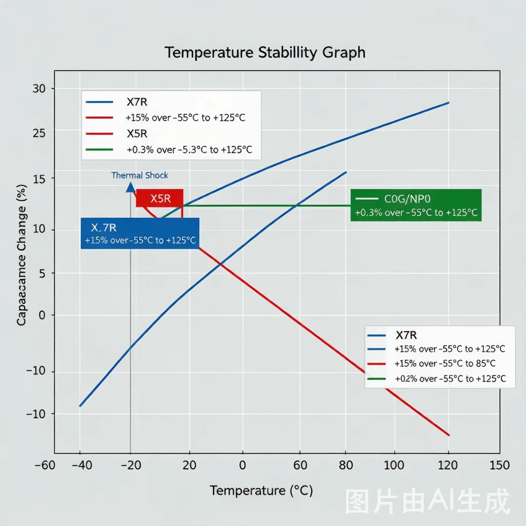
The dielectric determines how capacitance changes with temperature, voltage, and time. The EIA standard codes are:
Cross-referencing across dielectric classes is possible only when the circuit tolerance allows it. Replacing a C0G part with X7R in an RF matching network will shift the center frequency. Replacing X5R with X7R is usually acceptable if the temperature range requirement is met.
| Parameter | What to Match | Acceptable Variation | Red Flag |
|---|---|---|---|
| Package Size | EIA code (e.g., 0603) | ±0.05 mm on length/width | Different terminal geometry (reverse vs standard) |
| Capacitance | Nominal value at test condition | +20% / -10% for decoupling | >50% loss under DC bias vs original |
| Voltage Rating | Rated DC voltage | Higher is acceptable | Lower than original application voltage |
| Dielectric | EIA code (C0G, X7R, X5R, etc.) | Same class; X7R can replace X5R | C0G replaced by X7R in RF circuit |
| Case Thickness | Maximum height | Thinner is acceptable | Thicker than PCB clearance allows |
| Application | Preferred Dielectric | Key Cross-Ref Risk | Verification Step |
|---|---|---|---|
| RF matching network | C0G/NP0 | Dielectric loss (DF) variation between brands | Measure S-parameters with replacement part |
| Power rail decoupling | X7R, X5R | DC bias derating difference | Check capacitance at operating voltage |
| Timing (RC oscillator) | C0G/NP0 | Temperature coefficient mismatch | Verify TC over operating range |
| Bulk storage after LDO | X5R, X7R | Aging rate difference (Class II) | Check 1000 hr aging curve |
| Automotive (AEC-Q200) | X7R (AEC-Q200 qualified) | Non-qualified replacement | Confirm AEC-Q200 certification |
The following table shows representative MLCC part numbers from major brands. Use these as reference points when building cross-reference maps. For each application, identify the original part's four parameters, then search for equivalents using the AIMLCC Cross Reference Tool.
| Brand | Part Number | Package | Capacitance | Voltage | Dielectric | Link |
|---|---|---|---|---|---|---|
| Murata | GRM03370J_0000 | 0201 | See datasheet | See datasheet | C0G | View Part |
| Murata | GR321981E_0003 | 1206 | See datasheet | See datasheet | X7R | View Part |
| Murata | GR321980J_0008 | 1206 | See datasheet | See datasheet | X7R | View Part |
| Murata | GCM18852A_0002 | 0603 | See datasheet | See datasheet | X7R (AEC-Q200) | View Part |
| Samsung | CL03B0000 | 0201 | See datasheet | See datasheet | X7R | View Part |
| Samsung | CL21B0003 | 0805 | See datasheet | See datasheet | X7R | View Part |
| Samsung | CL21B0008 | 0805 | See datasheet | See datasheet | X7R | View Part |
| Samsung | CL10C0002 | 0603 | See datasheet | See datasheet | C0G | View Part |
| TDK | C1608X7R1C0000 | 0603 | See datasheet | See datasheet | X7R | View Part |
| TDK | C2012X7R1E0003 | 0805 | See datasheet | See datasheet | X7R | View Part |
| TDK | C2012X7R1C0008 | 0805 | See datasheet | See datasheet | X7R | View Part |
| TDK | C1608CH2A0002 | 0603 | See datasheet | See datasheet | CH (High Q) | View Part |
Additional cross-reference candidates from YAGEO, KEMET, and Walsin are available in the Brands directory. Submit an RFQ with your original part number to receive matched alternatives with full parameter comparison.
Q1: Can I replace a Murata MLCC with a Samsung part of the same capacitance and voltage?
A: Only after verifying dielectric type, DC bias derating, and temperature characteristic. Even with matching parameters, request samples for in-circuit validation because dielectric formulation differences affect high-frequency behavior.
Q2: Is AEC-Q200 qualification transferable between brands?
A: No. Each brand's AEC-Q200 qualification applies only to its own parts. A cross-referenced replacement must have its own AEC-Q200 certification from the component manufacturer.
Q3: Why does DC bias derating matter in cross-referencing?
A: Class II dielectrics (X7R, X5R) lose capacitance as DC voltage increases. Two parts with identical nominal capacitance can have very different DC bias curves. Always compare the bias curves at your operating voltage.
Q4: Can I use a higher voltage rated part as a replacement?
A: Generally yes, but check that the case thickness does not exceed PCB clearance. Also note that higher voltage parts in the same case size may have lower capacitance density due to thicker dielectric layers.
Q5: How long does cross-reference verification take?
A: Parameter matching can be done in minutes using the Cross Reference Tool. However, full validation including sample testing and DC bias verification typically requires 1-2 weeks depending on application criticality.
AIMLCC will check current stock, lead time and alternatives based on your part numbers or BOM.