A Multilayer Ceramic Capacitor (MLCC) is a surface-mount passive component that stores and releases electrical energy. It is the most widely used capacitor type in modern electronics, found in everything from smartphones and laptops to AI servers, electric vehicles, and 5G base stations. Billions of MLCCs are produced annually, and a single high-end smartphone may contain over 1,000 MLCCs on its main board.
MLCCs are valued for their small size, low equivalent series resistance (ESR), wide capacitance range, and ability to operate across a broad temperature spectrum. Unlike electrolytic capacitors, MLCCs are non-polarized and can be placed in either orientation on a PCB.
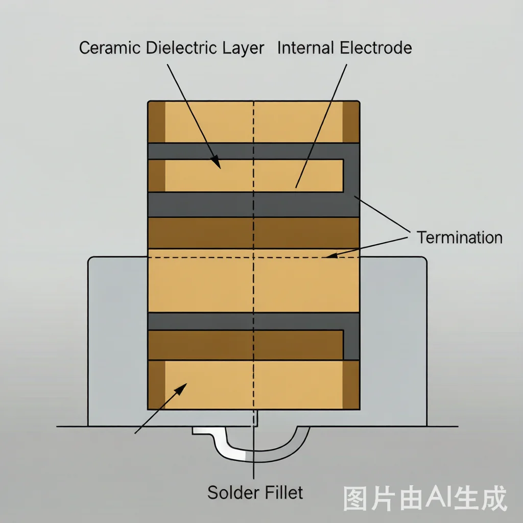
An MLCC consists of alternating layers of ceramic dielectric material and metal internal electrodes, stacked and co-fired into a monolithic chip. The external terminals (typically silver, nickel, and tin) are applied to the ends of the chip and connect to the alternating internal electrode layers.
This multilayer construction dramatically increases the effective electrode surface area within a given package volume. A 1 µF MLCC in an 0603 package may contain over 100 individual ceramic layers, each only a few microns thick. The total capacitance is proportional to the number of layers, the electrode area per layer, and the dielectric constant of the ceramic material.
The ceramic dielectric is the insulating material between the internal electrodes. It determines the capacitor's electrical characteristics — most importantly, its capacitance density, temperature stability, voltage coefficient, and aging behavior.
Internal electrodes are typically made of nickel (for base metal electrode, BME, MLCCs) or precious metals like palladium-silver (for precious metal electrode, PME, MLCCs). BME technology dominates modern production because nickel is cost-effective and compatible with high-temperature co-firing processes.
The external terminals are applied after firing. A typical terminal structure has three layers: a copper or silver base layer, a nickel barrier layer, and a tin finish for solderability. This three-layer construction ensures reliable solder joints and prevents silver migration.
When a voltage is applied across the terminals of an MLCC, an electric field builds up across each ceramic dielectric layer. This field causes polarization of the dielectric material — positive and negative charges separate and accumulate on opposite electrodes. The capacitor stores energy in this electric field.
When the applied voltage is removed or the capacitor is connected to a load, the stored charge flows out as electrical current. In a DC circuit, an MLCC blocks steady current flow after initial charging. In an AC circuit, the capacitor charges and discharges with each cycle, effectively passing AC current while blocking DC — a property used for coupling, decoupling, and filtering.
The Electronics Industries Alliance (EIA) classifies ceramic dielectrics into two main categories:
Class I dielectrics (such as C0G/NP0) are temperature-compensating ceramics based on materials like calcium titanate or magnesium titanate. They offer excellent stability: capacitance change is typically within ±30 ppm/°C, meaning near-zero drift over the full operating temperature range. Class I MLCCs have very low dielectric loss and are ideal for timing circuits, filters, precision analog circuits, and RF matching networks. However, their dielectric constant is relatively low, so they offer lower capacitance density than Class II types.
Class II dielectrics (such as X7R, X5R, X6S, Y5V) use ferroelectric ceramics, primarily barium titanate (BaTiO₃) with various additives. They provide much higher dielectric constants, enabling higher capacitance values in the same package size. The trade-off is that capacitance varies with temperature, applied DC voltage (DC bias), and time (aging). X7R, for example, guarantees capacitance change within ±15% over -55°C to +125°C, making it the workhorse dielectric for general-purpose decoupling, bypass, and filtering applications.
| Dielectric | Temperature Range | Capacitance Change | Typical Use |
|---|---|---|---|
| C0G / NP0 | -55°C to +125°C | ±30 ppm/°C (near zero) | Timing, filtering, precision analog, RF matching, medical |
| X7R | -55°C to +125°C | ±15% | General decoupling, bypass, filtering, automotive non-critical |
| X5R | -55°C to +85°C | ±15% | Power management, DC-DC converters, portable devices, consumer electronics |
| X6S | -55°C to +105°C | ±22% | High-capacitance, high-temperature applications where X5R range is insufficient |
When selecting a dielectric, consider both the temperature range and the DC bias characteristic. Class II dielectrics can lose 50% or more of their nominal capacitance under DC bias, and this effect is more pronounced in smaller package sizes. Always check the manufacturer's DC bias characteristic curve for the specific part number and operating voltage.
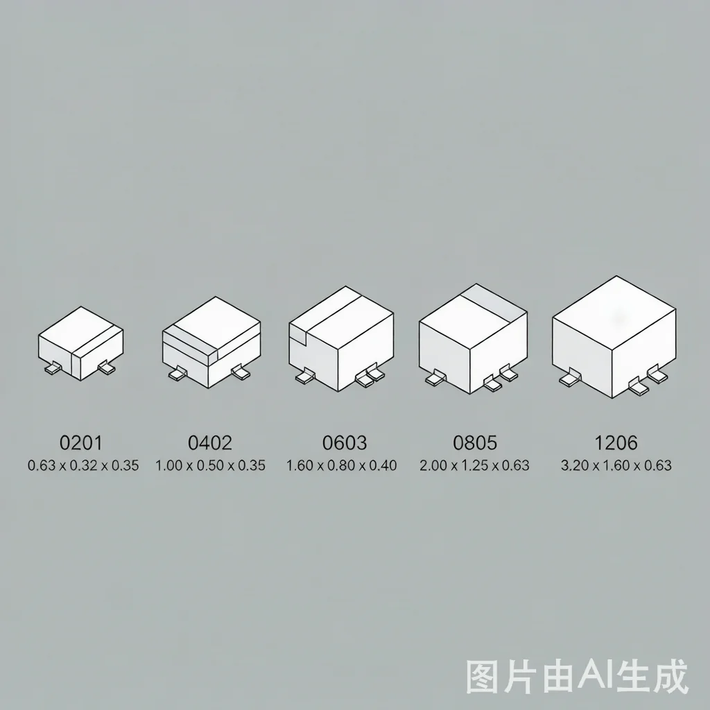
MLCC package sizes follow the EIA imperial code system (length × width in hundredths of an inch):
As package size decreases, the maximum capacitance and voltage rating also decrease. An 0201 MLCC might offer up to 1 µF at 6.3 V, while a 1206 MLCC can reach 100 µF at similar voltage. Package selection involves balancing board space, capacitance requirement, voltage rating, and the DC bias derating that is more severe in smaller packages.
AI Servers and Data Centers: GPU and ASIC power rails require massive decoupling networks with hundreds of MLCCs per board. High-capacitance X6S and X5R MLCCs in 0805 and 1206 packages handle bulk decoupling, while 0201 and 0402 MLCCs provide high-frequency bypassing directly under BGA packages.
Electric Vehicles (EV): Onboard chargers, DC-DC converters, motor inverters, and battery management systems use AEC-Q200 qualified MLCCs. Soft-termination and flex-mitigation types are specified for high-vibration environments.
Automotive Electronics: Engine control units (ECU), ADAS cameras, infotainment, and body electronics rely on automotive-grade MLCCs. X7R and C0G dielectrics are preferred for under-hood applications where temperature extremes are common.
RF and 5G Communications: Base station power amplifiers, filters, and antenna matching networks use high-Q C0G/NP0 MLCCs with ultra-low ESR. Frequency stability is critical, making Class I dielectrics essential.
Industrial Power: SMPS, motor drives, welding equipment, and factory automation require MLCCs with high voltage ratings (500 V to 3 kV) and robust construction. X7R and NP0 dielectrics are typical.
When sourcing MLCCs, three parameters must be evaluated together:
Failure to account for DC bias is one of the most common causes of power rail instability. What appears as "sufficient capacitance" on the schematic may be far less in practice.
When sending an RFQ for MLCCs, include the following information to receive accurate quotes:
MLCCs are non-polarized, have much lower ESR, smaller size, and better high-frequency performance. Electrolytic capacitors offer higher capacitance per volume for bulk energy storage but have polarity, higher ESR, and shorter lifespan. In modern designs, MLCCs have largely replaced electrolytics for decoupling applications, while electrolytics remain for bulk filtering at power supply inputs.
In many cases yes, if the operating temperature does not exceed 85°C and the DC bias and voltage characteristics are verified. X5R typically offers higher capacitance density and lower cost than X7R, but X7R provides a wider guaranteed temperature range (-55°C to +125°C vs -55°C to +85°C). Always check the application's actual ambient and board temperature before substituting.
Class II dielectrics (X7R, X5R, X6S) use ferroelectric barium titanate ceramics. When a DC voltage is applied, the electric field partially saturates the polarization of the ceramic domains, reducing the effective dielectric constant and therefore the capacitance. This is an inherent material property, not a defect. C0G/NP0 Class I dielectrics do not exhibit significant DC bias capacitance loss.
Choose the largest package that fits your PCB layout, consistent with your capacitance and voltage requirements. Larger packages (0805, 1206) suffer less DC bias capacitance loss, can handle higher voltages, and are easier to assemble. Use smaller packages (0201, 0402) only when board space is constrained or when low inductance is critical for high-frequency decoupling.
Not automatically. While EIA package sizes and dielectric codes are standardized, manufacturers differ in internal construction, electrode materials, termination plating, and reliability testing. A Murata GRM series MLCC and a Samsung CL series MLCC with the same nominal specifications may have different DC bias curves, ESR, and reliability margins. Always verify with datasheets and, for critical applications, conduct your own qualification testing.
AIMLCC will check current stock, lead time and alternatives based on your part numbers or BOM.
Quick RFQ